Internal leakage of air in ventilation systems is wasteful and it can also affect the indoor air quality so we need to minimise leakage to both optimise the energy consumption and ensure the best possible air quality. In this article, you will get to know different modes of internal leakages and how to avoid them.
We differentiate between internal and external leakage. Internal leakage occurs between the dividing walls of the internal sections and external leakage is the leakage through the unit casing between the inside and outside of the unit.
Air leakage through and around filters
All types of air handling units have a potential leakage of air past the filters which will have a negative impact on the air quality as well as dirty ducting with increased cleaning costs as a result. Filter bypass leakage is classified according to the filter grade with the intention that the design of the filter frame and sealing is appropriate for the filtration required. Testing should be carried out in accordance with EN 1886.
Fans, pressures and air leakages
Where the fan is installed, there will be a high pressure on one side of the dividing wall and a low pressure on the other side. Clearly, there is potential for leakage in the form of a backflow of air from the discharge of the fan to the intake. This leakage will result in higher energy consumption, higher fans speed and higher noise level.
Air leaking in coil sections
Where coils are installed there is a potential for leakage of air past the heat exchanger. There will be a shortfall of heating or cooling power but no actual energy loss. With cooling coils, such leakage can cause condensation downstream in extreme cases.
Heat exchangers and air leakage
Heat exchangers for energy recovery are also potential sources for leakage. Plate heat exchangers should have small levels of leakage in themselves but a poor installation in the air handling unit can give rise to considerable leakage with energy losses and degraded air quality as a result. Well installed plate heat exchangers will have very low leakage.
Rotary heat exchangers offer the advantage of a high efficiency with small space requirement and very little need for defrosting. But because they rotate they are more difficult to seal effectively.
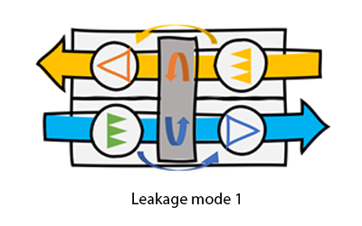
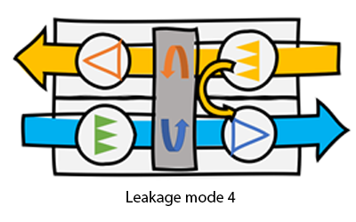
Rotary heat exchangers have four modes of leakages
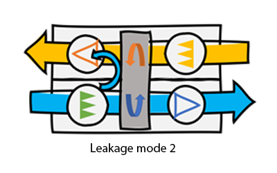
The first is the peripheral leakage. Leakage around the periphery of the rotor will have a direct effect on the overall heating power of the rotor. The reduction in temperature efficiency can be significant so it is important that the periphery seal is effective. The second mode of leakage is that from the outdoor air side to the exhaust air side. Normally there will be a large pressure difference between the outdoor air side of the rotor and the exhaust side. This pressure drop drives a leakage from the supply to exhaust air side. Leakage in that direction will not affect the air quality but it will have an effect on the energy consumption.
When we have the correct airflow at the supply air fan we will have a higher airflow at the fresh air filter and that means we will have a higher pressure drop there. We must also compensate on the exhaust side to ensure that we get the correct extract airflow. This is quite a complex calculation to make requiring an iteration to arrive at the correct result but without it, the power consumption of the fans will not be correct and that means any annual energy calculation will also be wrong.
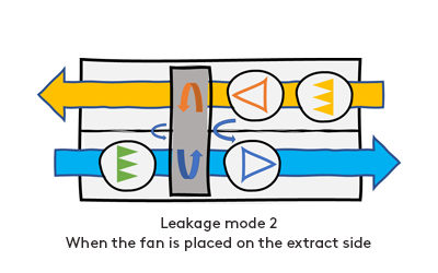
If the extract fan is placed on the extract side of the rotor then the leakage will be in the other direction. This will have a serious effect on the air quality and is not recommended at all.
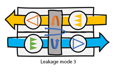
The third mode of internal leakeges occurs when the rotary heat exchangers carries extract air over to the supply air. This carry over leakage can be effectively eliminated by means of a purging sector. A small sector of the rotor is shielded off so that extract air can not enter the rotor there and outdoor air is bled through the rotor in both directions to purge it of extract air. This purging function cleans the rotor of impurities and ensures a high quality of supply air. To drive this purging flow we need a pressure difference; which must be created by the extract fan. The purging flow must also be added to the flow rate of the extract fan. The fourth mode of leakage is from extract to supply on the room side of the rotor like this. This leakage will depend on the pressure difference between the extract and the supply and if the fans are correctly positioned as shown, can be eliminated by throttling the extract air so that the pressure difference is in the right direction. This extra pressure drop must be included in the exhaust fan.
Internal leakages must be considered when calculating specific fan power
Only when all of these modes of leakage are accounted for can we have a correct calculation of the air handling unit and without it the SFP, the temperature efficiency and any annual energy calculation will not be correct. The ErP Regulation 1253 defines maximum limits for the internal SFP; which is called SFPint. We can expect that the definition of the SFPint will include the leakages.
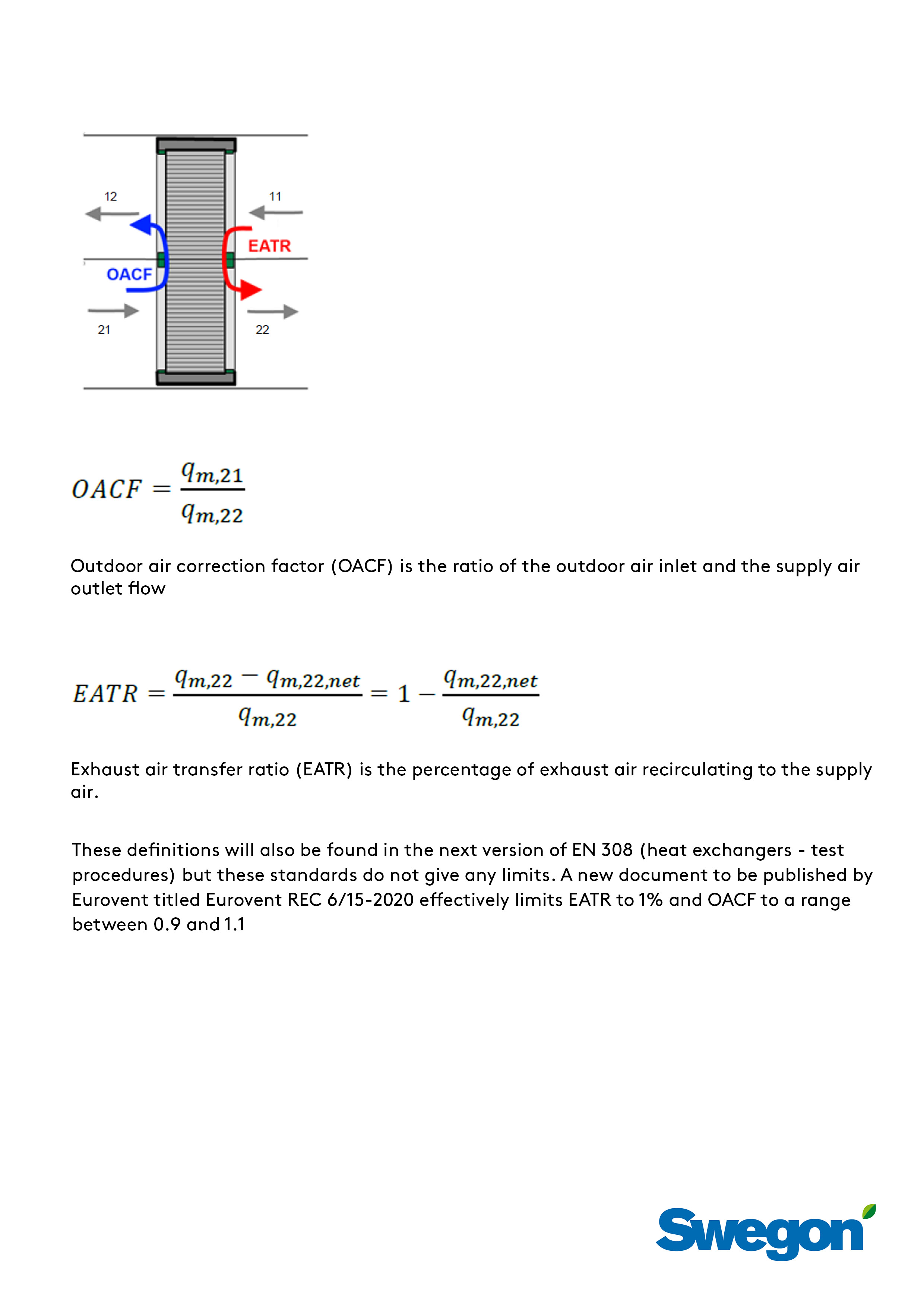
The leakages described in modes two to four above are defined in EN 16798-3:2018 (Energy performance of buildings) by two ratios: Outdoor air correction factor and Exhaust air transfer ratio.
Outdoor air correction factor (OACF) is the ratio of the outdoor air inlet and the supply air outlet flow, see the full definition. OACF should be greater than 1 because that means the leakage is from supply to exhaust. If it is less than 1 then there is leakage from exhaust to supply.
Exhaust air transfer ratio(EATR) is the percentage of exhaust air recirculating to the supply air, see the full definition. EATR is the leakage by the seal at the rotor on the room together with the carry-over leakage.
This how you design air handling units with minimal internal leakage
The fans in the air handling unit have to be in the correct position to minimise leakage. The rotors needs to be fitted with a purging sector and a control system that can adjust the rotor speed to minimise carry-over in the rotor at a low airflow rate which allows you to a safe use of the highest possible energy recovery.
Make sure that you have a software selection tool that can correctly calculate the leakage flows and includes them in the calculation of the fan performance. The outdoor air correction factor and the exhaust air transfer ratio must be included in the technical presentation of the unit.
Moreover, the air handling unit needs to be fitted with pressure measurement nipples and pressure reducing plates in the extract air so that the unit can be correctly adjusted to ensure minimum leakage to give an outstanding energy recovery and healthy indoor environmental quality.


