


Induction Process
Active Chilled Beam Cross Section
An active chilled beam is basically a cabinet with a water coil. There are no moving parts such as a fan and motor (i.e. fancoil). To get air in the space to pass through the coil, the induction principle is applied using primary air from a main air handling unit. The room air is “induced” to pass through the coil by creating a low pressure zone above the coil. As air passes through the coil, it can be heated or cooled using hot or chilled water. The induced air and the primary air mixed and delivered to the room via diffusers that are designed into the chilled beam to optimize mixing and take advantage of the coanda effect.

Induction Ratio
The ratio of induced air to primary air is the Induction Ratio. For example, if 1 cfm of primary air induces 3 cfm or room air to pass through the coil, the induction ratio would be 3 to 1 and 4 cfm would be delivered through the diffuser to the space.

Induction Process
The reason the induction process works can be seen in Bernoulli’s principle.

Said in words, if you increase the kinetic energy (the speed) of a fluid then its pressure must go down. In a chilled beam, the primary air passes through a nozzle bank and its speed increases, thus its pressure goes down and low pressure area is created downstream of the nozzle bank (above the coil).
This principle is how perfume atomizers and carburetors work, why sail boats can sail into the wind and of course, why airplanes fly.
To get room air to pass through a coil, work is being done and energy used. In a fancoil, the energy is electricity that the fan motor consumes to operate the fan. In a chilled beam the energy source is the primary air handling unit. The primary air must be delivered to the chilled beam and overcome the pressure drop of the nozzle bank. The nozzle bank requires more external static pressure at the air handling unit. Typically the fans and motors in air handling units are much more efficiency that mall fans and motors used in terminal products.
One way to look at the energy usage in a chilled beam is to consider the air flow rate (cfm) as equal to electrical current and the pressure drop of the nozzle bank as equal to voltage. Some combination of airflow are and pressure drop (i.e. voltage and current) will provide the necessary energy to draw room air through the coil.
Modern chilled beam design has advanced to the point where the pressure drop across the nozzle bank is less than a 0.25 inches w.c. and typically around 0.5 inches w.c. for the whole chilled beam (which includes the diffuser components.)
Induction Process in Swegon PACIFIC Chilled Beam
Induction Process in Swegon PARASOL Chilled Beam
Nozzles

Chilled Beam Slot Nozzle

Chilled Beam Round Nozzle
Nozzles come in all sorts of shapes and sizes. A orifice plate is a nozzle. Nozzle design in chilled beams has evolved to create the best induction result with the lowest pressure drop and noise level.
Nozzle selection is based a specific operating conditions and is very sensitive to changes in the design conditions. As primary air passes through a small opening it accelerates. In a very complicated fluid dynamics process, the shape of the jet profile, plenum geometry, jet velocity and other properties will create a low-pressure area I the plenum that will cause room air to be drawn into the plenum via the coil and then pass out through the diffuser slots back to the room.
If the building design requires a small amount of primary air (i.e. “low current”) then the chilled beam selection will use small nozzles to induce more room air but requiring a larger pressure drop (i.e. “high voltage”) to get enough room air to pass through the coil to meet the cooling and heating demands. In short, the induction ratio will go up.
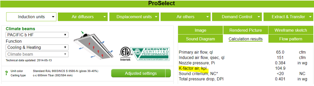
Nozzle K Factor
Changing the nozzle size and properties is known as changing the k factor. k factors are listed on the chilled beam printouts and can be used by the balancing contractor to measure the amount of primary air entering the chilled beam.

Where
q = (primary) airflow in cfm or l/s
K = k factor (note the k factor has a different value for SI or IP units)
P = the pressure drop across the nozzle bank in Pa or inches w.c.
If the chilled beam is manufactured with a fixed nozzle size (fixed k factor), then any changes in the design conditions in the future will be very limited. For example if the space ventilation rate, cooling or heating loads change appreciably, adjustments in the beam performance will be very restricted to the point where the beam may need to be replaced.

Adjustable Nozzles
Adjustable nozzles solve this issue by allowing the nozzle design to changed as the needs of the space evolve. You can change the K factor in the field. Adjustable nozzles must be built into the product at time of manufacture. Most nozzle adjustments can be achieved by hand or with hand tools.
Modulating Nozzles
The ultimate form of adjustability is a Demand Control Ventilation or VAV chilled beam where the nozzle adjustment is motorized and varies based on the amount of primary air entering the chilled beam. DCV chilled beams have variable k factors than maintain the induction process over a large primary airflow rate. As the primary airflow rate is reduced to save energy, the k factor changes and the induction process continues allowing space control. Click here to learn more Chilled Beam Design.
