ROOM UNIT
PARASOL Comfort Module
Integrated comfort modules with 4 way airflow for heating, cooling and ventilation. Optional integrated VAV for demand control ventilation.
PARASOL is a complete product family. The comfort modules are optimized to quickly mix the supply air with the room air, which provides better comfort in the room.
In heating applications, this technique can be utilized advantageously to convey heat from the ceiling in a better way and attain good comfort in the occupied zone.
A comfort module differs from a climate beam by distributing air in four directions instead of two. This maximizes the area for the mixture of supply air with the room air, which enables you to take out a high capacity, but without occupying more ceiling space than necessary.


Function Overview
|
PARASOL Classic |
PARASOL Zenith |
PARASOL Zenith DCV |
Cooling |
X |
X |
X |
Heating |
X |
X |
X |
Supply Air |
X |
X |
X |
Air Flow |
| ||
Constant (CAV) |
X |
X |
|
Variable (VAV) |
X | ||
Installation | |||
Integrated |
X |
X |
X |
*Please consult Swegon NA for suspended installation options
Key Features
PARASOL Classic |
PARASOL Zenith |
PARASOL Zenith DCV | |
Primary Airflow |
Up to 117 cfm |
Up to 233 cfm |
Up to 233 cfm |
Pressure Range |
0.2 – 0.6 in.wg |
0.2 – 0.8 in.wg |
0.2 – 0.8 in.wg |
Cooling Capacity |
Up to 7018 Btuh |
Up to 7012 Btuh |
Up to 7012 Btuh |
Heating Capacity |
Up to 9200 Btuh |
Up to 9213 Btuh |
Up to 9213 Btuh |
Sizes: | 24″ module: 24 x 24 in. 48″ module: 48 x 24 in. | 24″ module: 24 x 24 in. 48″ module: 48 x 24 in. 72″ module: 72 x 24 in. | 24″ module: 24 x 24 in. 48″ module: 48 x 24 in. 72″ module: 72 x 24 in. |
Heights |
8.66 in. |
9.8 in. (PF+11.4) in. |
9.8 in. (PF+11.4) in. |
Basic Operation

4 way Comfort Modules provide full coverage vs. 2 way chilled beams
Swegon PARASOL comfort modules have 4-way air discharge airflow with induction function. PARASOL comfort modules are active type using the primary air to induce room air through a coil to heat or cool the space without the need for fans. This delivers very quiet operation and minimal maintenance requirements. Unlike a 2-way air discharge chilled beam, air distribution to the room occurs from all 4 sides of the unit providing excellent mixing to all parts of the room. This ensures comfort level throughout the occupied zone. The PARASOL comfort modules are designed for dry systems, i.e. without condensation and therefore do not require any condensate drainage system or any filter. The minimum number of moving parts and lack of filter guarantees very little need for maintenance.
The PARASOL comfort modules are also optimized to quickly mix the discharge air with room air providing better comfort in the room. In heating applications, this technique can be advantageously utilized to efficiently provide heat from the ceiling. The PARASOL comfort modules are available in three basic variants:
Variant A: Primary air and water-based cooling from a coil (2 pipes)
Variant B: Primary air and water-based cooling and heating from the coil (4 pipes)
Variant C: Primary air only utilizing the PARASOL’s 4-way diffuser to mix additional ventilation air into space.
The PARASOL comfort modules operate according to the induction principle. Primary air (A) from the air handling unit provides PARASOL with supply air via a supply air duct and builds up positive pressure in the unit’s plenum. The supply air is forced out at high speed through nozzles (PARASOL Classic) or small slots (PARASOL Zenith). The high speed means that the surrounding air is drawn in and mixed with supply air, which generates negative pressure above the unit’s integrated heat exchanger (C). Room air (D) is continuously drawn up from the room through the water-based heat exchanger where, if necessary, it is cooled or heated before it mixes with the supply air.
The mixed air is then distributed to the room via aerodynamically designed outlets. The outlets are designed to ensure that the distributed air follows the suspended ceiling by utilizing the Coanda Effect (E). The supplied air is then mixed with additional room air, which further lowers the air velocity and reduces the temperature difference before it reaches the occupied zone.
LEARN MORE
Induction Process
Active chilled beams utilize the induction process to cause room air to pass through the chilled beam to heat and cool the air and create a comfortable environment.

PARASOL Airflow and Capacity Control

PARASOL Classic Nozzles
The unique built-in nozzle control in the PARASOL classic means that each of the four sides can be set individually. Depending on the unit’s location and the room’s primary air requirement, the primary air can be guided in all the desired direction. The direction of the airflow can be easily optimized using the Swegon ProSelect Sizing Program.
All units are preset to the same nozzle setting on all four sides. The airflow direction can be easily commissioned when installing the unit. This provides logistic advantages since the installer does not have to take specific room markings into account.
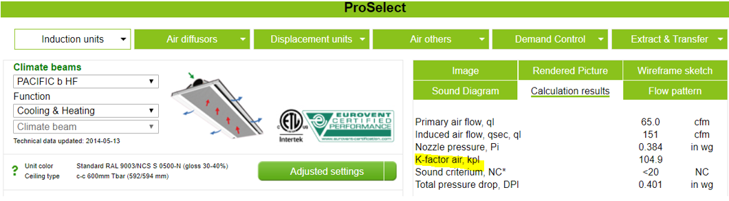
Each nozzle setting has a specific k-factor. There are four nozzle ranges (LF, MF, HF and PF) and each range has three nozzle settings.
A total k-factor for the unit can be determined by adding together the k-factors for the nozzle settings on each side. The relevant k-factor for an optimized nozzle setting can also be obtained in ProSelect.
Optimizing nozzle settings can be preset in the factory or field changed.
PARASOL Zenith provides unique advantages with its slot control and through this a large working range on the airside. PARASOL Zenith is designed to handle a large airflow range in one model. This gives benefits such as easy sizing and a straightforward product upgrade path. PARASOL Zenith can be easily set to the required k-factor with the help of the knob located on the short side opposite the short side with water connections. A special strip can be field added to block off one of the sides if required.
PARASOL Zenith Nozzles


PARASOL Zenith Nozzle Adjustment Knob

ADC in PARASOL Zenith
Both PARASOL classic and Zenith include ADC as standard. ADC enables the diffusion pattern of the air being distributed to be set to avoid the risk of draught. ADC can also be used to reduce the throw length. By setting ADC to L-shape, the distance between two units can be reduced to a minimum and still ensure a good comfort level.
A number of ADC sections with nine air deflections per section are arranged on each side of the unit. Each section is adjustable from a straight setting to 40-degree air deflection to the right or left in increments of 10 degrees. This provides great flexibility and can be adjusted without having to affect the system as a whole.
The direction of the air can be easily adjusted and gives future-proofing, offering a simple measure on location for any change to the furnishings and layout. The ADC does not affect the sound level or static pressure at all
LEARN MORE
Anti Draught Control (ADC)
Delivering a comfortable environment is more than just heating and cooling the space, it requires well distributed air. Swegon Anti Draught Control (ADC) helps change air flow patterns for the best comfort level.
PARASOL Comfort Module Adjusts to Meet Changing Space Requirements
PARASOL – Additional Features
The return air grille on the PARASOL can be easily released to allow access to the coil for inspection and cleaning. The grille is secured to the beam with a cable for added protection.

PARASOL Coil Access
Custom hole patterns in the grilles are available with PARASOL comfort modules. A range of standard colors is also available for PARASOL comfort modules For more information Contact Swegon or your local sales office.

PARASOL Custom Return Air Grilles


PARASOL comfort modules are available in multiple colors
Certification


The Swegon PARASOL Classic and Parasol Zenith are Eurovent certified, which is your guarantee that all specified data has been confirmed by tests and has been validated. This includes data provided in Swegon’s selection software, Proselect Web. Click here to learn more about Chilled Beam Certification.
In Addition, the PARASOL Classic and Zenith comfort modules are certified by Intertek to UL 1995- Heating and Cooling equipment and CAN/CSA C22.2
Applications
The PARASOL comfort modules are designed for use in most T-bar ceiling systems and clip-in ceilings in terms of length and width. PARASOL is a good fit in standard suspended ceiling grids. In addition, there is a mounting frame for drywall ceilings.

PARASOL classic chilled beams


PARASOL Chilled Beam installed in Drywall Ceiling
PARASOL Classic can be fabricated with EX casing for suspended installation in open ceilings. The EX casing has an integrated coanda wing for proper mixing of room and supply air. Casing covers with the same finish are available to cover the primary air duct and water lines.

PARASOL classic EX Comfort Module

PARASOL EX Flow Pattern
PARASOL EX Flow Pattern
For PARASOL Zenith and PARASOL Zenith DCV, beam casings can be built with finished painted casing and coanda wings for open ceiling applications.

PARASOL Zenith with Coanda Wings
For applications with elevated hygiene demands such as labs and healthcare, the PARASOL comfort module can come with an optional drop coil so both sides of the coil can be accessed for cleaning. The water connections are not interrupted.


PARASOL Zenith with optional drop coil


PARASOL Classic 2×2 and 2×4 Comfort Modules
PARASOL classic is supplied as standard with an open air connection on the right-hand side (seen from the side where the water is connected). The air connection piece is supplied and must be installed so that it can be connected to the primary air duct. A cap is fitted at the factory to the left-hand air connection, but the connections can easily be switched if the air connection inlet has to be fitted to the left.

Parasol classic air connection piece
PARASOL Zenith and Zenith DCV are equipped with alternative air connections to simplify the duct installation and reduce the number of duct bends which save installation time and material cost while the pressure drop and noise generation are also reduced. Air connection can be on either long sides or one of the short sides.

PARASOL Zenith installation example: air connection on the short side of the beams for straight air connection on site.

When ordering, depending on the length, it is possible to choose connection side 1, 2, 3 or 4 as set out in the table below

PARASOL Zenith alternative air connections (view from above)
Position 1 = Short side connection
Position 2 and 4 – Long side connection.
PARASOL Zenith DCV Comfort Module
The PARASOL Zenith product can be used in either a constant volume or Demand Control Ventilation (DCV) primary air system. Demand Control Ventilation means the primary airflow can be varied (Variable Air Volume or VAV) offering many advantages over constant volume systems including energy savings, improved thermal comfort without sacrificing IAQ and the ability to apply diversity to the primary air system design to reduce capital cost. For more information on Demand Control Ventilation (DCV) chilled beam design click here.
To convert the PARASOL Zenith comfort module from constant volume to DCV the K factor adjustment knob is replaced with an actuator. This can be done at the time of order or after the product has been installed allowing the future option of converting to a DCV system.

PARASOL Zenith with Manual K factor Adjustment Knob

PARASOL Zenith with K factor Adjustment Actuator (DCV)
The PARASOL DCV comfort module is designed for easy integration with any BMS system. The BMS system typically has one zone controller per control zone. A control zone may be a single office space with one comfort module or a larger areas such as a classroom with multiple comfort modules. The Zone controller will have sensors (temperature, CO2, humidity etc.) monitoring the space and will operate one or all comfort modules in unison to meet the space requirements. The actuator requires 24 VAC and accepts a 0-10Vdc signal from the BMS system. The power supply and 0-10Vdc signal are wired to a terminal strip to simplify connections for the BMS contractor.

Multiple PARASOL VAV Comfort Module with Field Mounted BMS Zone Controller
Increasing the voltage signal will open the nozzles and allow more primary air to pass through the comfort module. Being able to vary the primary airflow, chilled water flow and hot water flow to a control zone offers the maximum flexibility to deliver the best IEQ at the lowest energy cost. The primary airflow is typically varied to meet the most demanding requirement for:
- Demand Control Ventilation (DCV) (CO2 level)
- Thermal Comfort (Zone temperature)
- Humidity Control (Hi humidity will increase primary airflow to dry the zone out)
When DCV chilled beams are used, the primary air system will be variable air flow. The fans in the primary air handling unit will be variable and typically controlled by duct static pressure. When there is lower demand in the building and the DCV chilled beams reduce the primary airflow requirement, the primary air handling unit will also reduce the flow offering significant energy savings through the year.


React M Airflow Sensor
Varying the primary airflow rate also means that the inlet static pressure to the chilled beams will change throughout the day. To provide stable air flow to a control zone, Swegon offers the React M primary airflow sensor that can be used to measure the airflow entering the control zone. It can be used for a small zone with a single comfort module or a large space with multiple comfort modules. The React M sensor is available for rectangular and round ducts.

Multiple PARASOL VAV Comfort Modules in a Control Zone
The React M sensor is connected to the BMS zone controller allowing the sensor to measure the primary air entering the control zone. The BMS can then open or close the Comfort Module nozzles to maintain a constant primary airflow regardless of main duct static pressure. This delivers true independent control to the space.
| Recommended limit values | PARASOL Classic, PARASOL Zenith & PARASOL Zenith DCV |
| Pressure Levels | |
| Max recommended coil operating pressure : | 230 PSI |
| Max. recommended coil test Pressure: | 350 PSI |
| Water flow (ensures evacuation of any air pockets in the system) | |
| Min. cooling water flow: | 0.475 GPM |
| Min. heating water flow: | 0.206 GPM |
| Temperature differentials | |
| Chilled Water Delta T | 3.6 – 9 degree F |
| Hot Water Delta T | 7.2 – 18 degree F |

PARASOL chilled beam performance can be calculated using Swegon’s Proselect Software. The Swegon application team can assist with your chilled beam applications ranging from selections to full system design review with our DesignEdge service. The following are recommended operating ranges for PARASOL chilled beam selections.
LEARN MORE
Swegon ProSelect Software
Web-based software for easy dimensioning and selection of room products: induction units, air diffusers, displacement units and products for demand-controlled ventilation.
| Recommended limit values | PARASOL Classic, PARASOL Zenith & PARASOL Zenith DCV |
| Pressure Levels | |
| Max recommended coil operating pressure : | 230 PSI |
| Max. recommended coil test Pressure: | 350 PSI
|
| Water flow (ensures evacuation of any air pockets in the system) | |
| Min. cooling water flow: | 0.475 GPM |
| Min. heating water flow: | 0.206 GPM
|
| Temperature differentials | |
| Chilled Water Delta T | 3.6 – 9 degree F |
| Hot Water Delta T | 7.2 – 18 degree F |
Installation Details

Parasol Classic Installation
The PARASOL Classic and Zenith are designed for installation flush-mounted in the majority of false ceilings available in the market.
T-section grid systems with IP units (NA)
- Width: 23.6 in.
- Lengths: 23.6, 47.6, 71.6 (Zenith only) in.
T-section grid systems with 600 mm c-c and gypsum ceiling
- Width: 592 mm
- Lengths: 592, 1192, 1792 (Zenith only) mm
T-section grid systems with 625 mm c-c and gypsum ceiling
- Width: 617 mm
- Lengths: 617, 1242, 1868 (Zenith only) mm
T-section grid systems with 650 mm c-c and gypsum ceiling
- Width: 642 mm
- Lengths: 642, 1292, 1842 (Zenith only) mm
T-section grid systems with 675 mm c-c and gypsum ceiling
- Width: 667 mm
- Lengths: 667, 1342, 2017 (Zenith only) mm
Clip in ceiling / sheet metal modules 600 c-c mm
- Width: 598 mm
- Lengths: 598, 1198, 1798 mm
Clip in ceiling / sheet metal modules 625 c-c mm
- Width: 623 mm
- Lengths: 623, 1248, 1873(Zenith only) mm
PARASOL Suspended by Cables
The PARASOL climate module is supplied with four mounting brackets and self-tapping screws for each unit. The mounting brackets are field installed in the corners. The pre-punched holes in each mounting bracket simplify the fastening work. The mounting brackets are designed to be turned in any optional direction depending on the type of suspension system selected. Turned inward, the mounting brackets offer simple installation by means of mounting strips. Turned outward, the mounting brackets work at their best for suspending the beams by means of threaded rods. Cable suspension is also a common means to suspend chilled beams.

PARASOL Drywall Ceiling Frame
A drywall plaster flange kit is available for installing PARASOL comfort modules in a drywall ceiling. The kit snaps to the module hiding the plaster edge and providing a clean, finished look.
PARASOL Classic Air and Water Connections

PARASOL Classic 2×2 Air Connections
PARASOL Classic 2×4 Air Connections
The PARASOL Classic comfort module can have the air connection on either the right or left side as seen from the water connection end. This can be changed in the field. The air connection size is 5 inch diamter for LF, MF and HF and 6 inch for PF.

PARASOL Classic 2×2 Water Connections

PARASOL Classic 2×4 Water Connections
The PARASOL Classic water connections have 12 mm copper tubing connected to a 1/2 NPT threaded fitting. The coil can be either 2 pipe or 4 pipe as required. Stainless steel flex hoses are available to quickly connected the comfort module to the building heating and cooling systems.
PARASOL Zenith Air and Water Connections
The PARASOL Zenith air connections can be on any of the 4 sides for simpler field installation. The connection location can be changed between L1 (water connection end), L2 and L4. It is not possible to change the connection location if L3 (opposite water connections) is selected. The connection size is 5”, 6” or 8” round depending on the beam size.

PARASOL Zenith Air Connections

PARASOL Zenith Water Connections
The PARASOL Zenith water connections have 12 mm copper tubing connected to a push on 1/2 NPT threaded fitting. The coil can be either 2 pipe or 4 pipe as required. Stainless steel flex hoses are available to quickly connected the comfort module to the building heating and cooling systems. The hoses include a 12 mm push on connection for the comfort module end and either 1/2 NPT, compression or 1/2 inch push on connection for the building side.
PARASOL Zenith Quick Bracket


PARASOL Zenith Quick Bracket
Swegon offers an additional installation method for Zenith to help reduce installation labor and ease comfort module installation. The Quick Bracket comes in a pair per comfort module. The comfort module will click into the bracket without the need for tools. further adjustment allows the module to be quickly adjusted to align with the suspended ceiling system. Parasol Zenith’s unique shape allows it to be installed through most ceiling systems without the need to remove the grid thus saving valuable time and cost.
Parasol Zenith Installation
Dimensions
Click on the tabs below to learn more
Find Documents
You can find more documents on our document search page.
| Link | Title | Article | Product Group | Document Type | Format | hf:tax:document_type |
|---|---|---|---|---|---|---|
| Installation Instructions – WCD2 | WCD2 PARASOL Installation | PARASOL, Room Units | Instructions | instructions | ||
| Installation Instructions -PARASOL Plaster Flange | PARASOL Plaster Flange | PARASOL, Room Units | Instructions | instructions | ||
| Parasol Classic | PARASOL | PARASOL, Room Units | Product Sheet | product-sheet | ||
| Operation and Maintenance | PARASOL | PARASOL, Room Units | Instructions | instructions | ||
| Parasol Zenith Brochure | PARASOL | Brochure | brochure | |||
| ETL Certification Parasol | PARASOL | PARASOL, Room Units | Quality | quality | ||
| GOLD SYSTEM APPLICATION Chilled Beams | GOLD | Air Handling, GOLD, PACIFIC, PARAGON, PARASOL, PRIMO, Room Units | Product Sheet | product-sheet |